1Open IFC Merge
Launch IFC Merge on your Windows computer. The main window has a file-management panel on the left, a 3D viewer on the right, and output and merge controls below the file list.
A practical guide to loading, reviewing, aligning, and merging IFC files with the built-in 3D viewer.
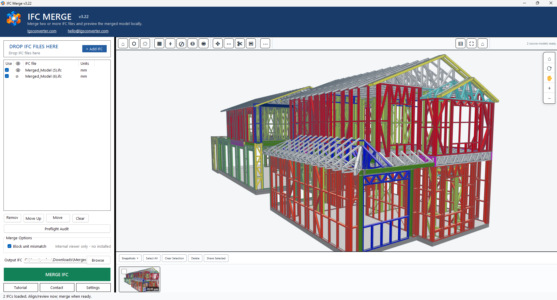
IFC Merge is a Windows desktop tool for loading multiple IFC files, reviewing their placement in a built-in 3D viewer, and exporting a merged IFC model.
Launch IFC Merge on your Windows computer. The main window has a file-management panel on the left, a 3D viewer on the right, and output and merge controls below the file list.
Drag IFC files into the Drop IFC Files Here area, or select Add IFC and browse to the files. Added files appear in the left-hand list.
Use the file list to check the source names and units. You can enable or disable a file, toggle its visibility with the eye control, and change the list order. Confirm that the intended files are active before merging.
Use the built-in viewer to orbit around the model, zoom into details, inspect framing, and compare how the loaded models sit together. Fit or reset the view if the model is outside the current view.
When source files use a shared coordinate system, their geometry should appear in the expected relative positions. Look for unwanted offsets, rotation, or missing geometry before continuing. If placement is wrong, use the placement tools.
Use Move when a model needs to shift. Select the model, activate Move in the placement controls, choose a snap point on the moving model, and then choose the matching point on the reference model.
Use Rotate when a model is positioned in the right area but faces the wrong direction. Select the model, activate Rotate, choose a rotation plane if offered, set the reference point, and complete the rotation.
Use Align to match a point or edge on one model to a corresponding reference on another. Select the model to move, start Align, pick the source reference, pick the matching target, and confirm the placement.
Open the Section controls to inspect inside the model. Depending on the current view and selected mode, the tools can include Pick Face, Horizontal, Vertical X, Vertical Z, Flip, and Off.
Section cuts can help review internal wall, floor, or roof framing and model coordination.
Choose Pick Face, move the cursor over the model, and select the face that should define the clipping plane. The viewer creates a section plane from the selected face.
Activate the Measurement tool, select the first point, and then select the second point. Review the displayed distance as a visual check; confirm important dimensions against your project source data.
When measurements are no longer needed, select and delete individual measurements or use the available clear command in the measurement controls. The exact control depends on the active viewer state.
Double-click a member or object in the viewer, then open the Properties panel. Available information can include IFC type, Express ID, GlobalId, name, description, tag, source file, and pick coordinates.
Use the snapshot area to keep important review views. Depending on the current selection, controls may include Select All, Clear Selection, Delete, and Share Selected.
Select Preflight Audit before export to review merge readiness. Treat it as an additional check, not a substitute for visually inspecting the source and merged models.
Use the Output IFC field at the bottom of the left panel. Enter a destination file path or choose Browse to select where the merged file should be saved.
Confirm the intended source files are enabled, check placement and visibility, set the output path, and select MERGE IFC to export the combined model.
Open the output in the viewer or your usual IFC software. Confirm expected geometry is present, placement is correct, and the result matches the source models before sharing or using it downstream.
Confirm the file is enabled, check its visibility control, and fit the view if needed.
Check source units and coordinate placement. Use Move, Rotate, or Align, then inspect the result again.
Check the selected output path, folder permissions, and that at least one source IFC is enabled.
Turn the current tool off and apply it again. Recheck the relevant viewer settings and the selected geometry.
For help or feedback, email hello@lgsconverter.com or visit the IFC Merge page.