LGSConverter is a cloud-based platform that converts light gauge steel (LGS) framing models — delivered as IFC, FRAMECAD XML, FRAMECAD FCP, or Machine CSV files — into the machine CSV output required to drive roll-forming equipment directly on the factory floor.
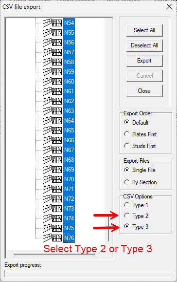
For FRAMECAD Structure Type 2 or Type 3 CSV exports, CSV Mapping edits selected values in your browser, then verifies billable length on the server before delivering a combined CSV or per-thickness ZIP without changing geometry.
Separate product: RFY MAPPER
RFY MAPPER is a separate Windows product for supported FRAMECAD .rfy files. It has its own PAYG balance and purchase flow; it does not use LGSConverter conversion entitlements. For RFY instructions, see the RFY MAPPER User Manual.
🏗️
No Detailer licence required
Fabricators can export machine-ready CSVs without a FRAMECAD Detailer seat.
🔍
Full 2D Frame Editor
16 editing tools — trim, extend, flip, box, measure, annotate and more.
✅
Export Validation
Verify all tooling marks before committing to CSV, with 3-way status filter.
⚙️
Machine Profiles
DAHEZB, PINNACLE and fully custom profiles with per-profile tool code mapping.
💾
Session Save (.lgs)
Save your entire editing session — frames, edits, exclusions — as a .lgs file and resume later.
🖥️
Desktop Application
Windows installer for offline-capable conversion with a local license key.
Issue 6 — What's new
This documentation update clarifies that RFY MAPPER is a separate Windows product with separate PAYG billing and links to its dedicated user manual. Issue 5 added the FRAMECAD CSV Mapping tutorial; Frame Editor tool reference; Bulk Settings; .lgs session save/resume; custom machine configurations; Export Validation filters; and clickable frame/member rows in the Validation Report.
2Supported File Formats
Format
Extension(s)
Source
Notes
IFC
.ifc
Any BIM tool (Revit, Tekla, ArchiCAD, FRAMECAD Structure)
Metric and imperial units auto-detected. Full multi-panel projects supported.
FRAMECAD XML
.xml, .zip
FRAMECAD Detailer
Single-panel XML or full project ZIP. Clone panels detected and preserved.
Inspect and re-map existing CSVs to a different machine profile.
FRAMECAD .rfy files
.rfy files are not an LGSConverter input format. Use the separate RFY MAPPER Windows app for that workflow; do not confuse its LM balance or purchases with LGSConverter billing. See the RFY MAPPER User Manual.
File size limits
Format
Max upload size
IFC
200 MB
XML / ZIP
100 MB
FCP
100 MB
CSV
20 MB
3Uploading & Converting a File
Log in to LGSConverter and navigate to the Converter tab.
Click the upload area or drag-and-drop your file (.ifc, .xml, .fcp, .csv, or .zip).
LGSConverter detects the format automatically and begins parsing. A progress indicator is shown during conversion.
Once conversion completes, the Frame Editor opens automatically with all frames listed on the left.
Review and edit frames, configure your machine profile, then generate your machine file.
IFC caching
IFC files are cached server-side for faster re-conversion. If you re-upload the same IFC after modifying the source model and do not see your changes, rename the file before uploading to bypass the cache.
Resuming a previous session
If you saved a .lgs session file from a previous conversion (see Section 6), you can reload it by dropping it onto the upload zone instead of re-uploading the original source file. All your previous edits, exclusions, and tool mappings will be restored immediately.
4Frame Editor — Complete Tool Reference
The Frame Editor is the central review and editing interface. It displays every frame from your converted file in 2D elevation view, with all members rendered to scale alongside their tooling marks.
4.1 Toolbar Overview & Keyboard Shortcuts
The toolbar runs across the top of the canvas. Click any tool icon to activate it, or press the matching keyboard shortcut. The currently active tool is highlighted with a blue background.
Tool
Shortcut
Description
Select
—
Click to inspect a member. Opens the Member Inspector on the right.
Move
M
Drag a selected member to a new position, or enter a precise offset in mm.
Flip
F
Toggle the lip-side orientation of a stud (face inside / outside).
Box
B
Toggle back-to-back C (boxed stud) on a selected member.
Trim
T
Shorten a member end to align with an adjacent member's flange face.
Extend
E
Lengthen a member end toward an adjacent member's flange face.
Lengthen
L
Add or subtract an exact offset from a member end; diagonals keep their angle.
Measure
D
Click two points to display the distance between them in mm.
Delete
—
Remove a member from the frame permanently.
Add Stud
—
Click the canvas to place a new vertical stud at that position.
Add Plate
—
Click the canvas to place a new horizontal plate or nog.
Break
—
Split one member into two independent pieces at the click point.
Service Hole
—
Draw a service hole run from start to end point; exported to CSV.
Bolt
—
Draw a bolt hole run from start to end point; exported to CSV.
Web Notch
—
Draw a manual web notch line; exported to CSV.
Chamfer
—
Place a user-defined END_TRUSS chamfer mark at a member endpoint.
Additional keyboard shortcuts
Key
Action
Ctrl+S
Save the current session as a .lgs file (download prompt).
S
Toggle snap mode between 90° constrained and free-angle.
Z
Flip the elevation view (mirror the canvas left-to-right).
Space
Re-activate the last-used tool (if it was not Select).
Escape
Cancel the current annotation, measurement, or multi-click action.
Tip — Canvas navigation
Pan the canvas by clicking and dragging on empty space. Zoom in and out using the scroll wheel or a pinch gesture. The current zoom level is shown in the top-right corner. Click Fit (F in the zoom control) to auto-fit all members on screen.
4.2 Select Tool
The Select tool is the default tool when the editor opens. Click any member on the canvas to select it and open the Member Inspector panel on the right. The inspector shows:
Member name and role (Stud, Plate, Nog, TopChord, BottomChord, Web, Brace, Rail, etc.)
Profile dimensions — web × flange × lip in mm
Start and end positions in mm from the frame origin
Flipped flag — controls which side the lip faces relative to the panel face
All assigned tooling marks — type, station (mm from start), and orientation
Click an empty area of the canvas to deselect and close the inspector.
4.3 Move Tool M
The Move tool lets you reposition a member laterally within the frame. Activate the tool, then click the member you want to move. You can:
Click and drag the member to a new position on the canvas.
Type a numeric offset in mm in the input box that appears in the toolbar for precision placement.
Moving a member triggers an automatic re-tooling pass — all connection marks are recomputed immediately.
4.4 Flip Tool F
The Flip tool toggles the flipped orientation flag on a selected stud or member. Flipping swaps which face the C-section lip opens toward — this controls which side of the member the web notch and swage marks are placed on in the machine CSV.
When to use Flip
Use Flip when a stud's lip direction does not match the FRAMECAD Detailer convention — for example, if a nog or brace is rendering its tooling on the wrong face. Most members are assigned the correct orientation automatically during conversion.
4.5 Box Tool B
The Box tool toggles a back-to-back C (boxed section) on any selected member. A boxed stud is two C-sections placed web-to-web, creating a closed-box column. When Box is active on a member:
The member is rendered as a double-section on the canvas.
The CSV export emits both C-sections as separate rows with their respective tooling marks.
4.6 Trim Tool T
The Trim tool shortens a member from one of its ends. Trimming snaps the member end to the flange face of the nearest adjacent member — the same snap plane used by FRAMECAD Detailer.
How to use:
Press T or click the Trim tool in the toolbar.
Click the cutting boundary — the adjacent member whose face you are trimming back to.
Click the member end you want to shorten. The end snaps flush to the boundary member's flange face.
Trim only applies to axis-aligned (horizontal or vertical) members. Diagonal members use the Lengthen tool instead. After trimming, tooling marks are automatically recomputed.
4.7 Extend Tool E
The Extend tool is the opposite of Trim — it lengthens a member end toward an adjacent member's flange face. Use it to restore a member that has been trimmed too short, or to extend a member to meet a plate it does not currently reach.
How to use:
Press E or click the Extend tool.
Click the target boundary — the member you are extending toward.
Click the member end you want to lengthen. The end extends to meet the boundary member's flange face.
Trim vs Extend — choosing the right tool
If the member end currently overlaps the boundary → use Trim to pull it back. If the member end currently falls short of the boundary → use Extend to push it out. Both tools snap to the same flange-face plane, so the result is identical regardless of which direction you start from.
4.8 Lengthen Tool L
The Lengthen tool adjusts a member by a user-specified offset in mm. Unlike Trim/Extend, it works on all member orientations including diagonals, and the offset is entered numerically rather than by clicking a boundary.
How to use:
Press L or click the Lengthen tool.
Click the member you want to adjust. The Member Inspector opens showing the current length.
Type the desired new total length (in mm) in the input field, then press Enter. The member updates immediately, preserving its angle if it is diagonal.
4.9 Measure Tool D
The Measure tool displays the distance between any two points on the canvas.
Press D or click the Measure tool.
Click the first point. A snap indicator appears.
Click the second point. The distance in mm is displayed on the canvas as a dimension line.
Press Escape to clear the measurement.
Measurement snaps to member endpoints and midpoints. Multiple measurements can be placed simultaneously for comparison.
4.10 Delete Tool
The Delete tool permanently removes a member from the current frame. Activate it and click any member to delete it. The deletion triggers an immediate re-tooling pass on all remaining members.
Deletion is not undoable in the current session
Deleting a member cannot be reversed with Ctrl+Z. If you need the member back, close the editor without saving, or reload from a previously saved .lgs file. For structural members (chords, plates), check the QA Summary after deletion for any connection coverage warnings.
4.11 Add Stud / Add Plate
These two tools let you place new members into a frame without re-uploading the source file.
Add Stud — click on the canvas to place a new vertical stud at that horizontal position. The stud spans the full height of the frame by default. Profile dimensions are inherited from the nearest existing stud.
Add Plate — click on the canvas to place a new horizontal plate (nog) at that vertical position. Width and profile are inherited from the nearest existing plate.
Newly placed members are tooled automatically on the next connection-detection pass.
4.12 Break Tool
The Break tool splits one member into two independent pieces at the click point. Both halves retain the original member's profile and role, and both receive independent tooling marks.
Common uses: splitting a long plate around an opening; separating a stud that crosses a level change.
4.13 Service Hole Tool
The Service Hole tool draws a run of service penetration holes along a stud or plate. These are exported directly to the machine CSV as SERVICE HOLE operations.
Click the Service Hole tool in the toolbar.
Click the start point of the service hole run on the canvas.
Click the end point. A dashed run indicator is drawn on the member.
The hole run is saved with the frame and included in all subsequent CSV exports.
Bulk service holes via Settings
For adding service holes to many studs at once — for example, a single horizontal run at a fixed RL across all studs in a wall — use the Settings panel instead. See Section 5.
4.14 Bolt Tool
The Bolt tool draws a run of bolt holes along a plate or stud, exported as BOLT operations in the machine CSV.
Click the Bolt tool in the toolbar.
Click the start point of the bolt run.
Click the end point. A bolt run indicator appears on the member.
Bulk bolt holes via Settings
For applying bolt holes uniformly across all bottom plates in a wall — with a configurable maximum spacing — use the Settings panel (Section 5).
4.15 Web Notch Tool
The Web Notch tool places a manual web notch annotation on a member — overriding or supplementing the automatic tooling engine. This is used when a geometric crossing is not detected automatically (for example, a non-standard penetration).
Click the Web Notch tool in the toolbar.
Click the start point of the notch on the member.
Click the end point. The notch is rendered as a red line on the canvas and exported to CSV.
4.16 Chamfer Tool
The Chamfer tool places a user-defined END_TRUSS chamfer mark at a member endpoint. Chamfer marks are seat cuts at the ends of sloped truss chords where they bear on a supporting plate.
Chamfer marks are normally added automatically by the tooling engine for sloped chords. Use this tool only when a chamfer is missing from the automatic output — for example, on a non-standard truss geometry.
4.17 Excluding Frames & Clone Frames
Excluding frames
Toggle the Exclude checkbox next to any frame name in the left-hand list to remove it from the machine CSV export. Excluded frames remain visible in the editor with a strikethrough label. The running linear-metre total in the header updates in real time to reflect only included frames.
Clone frames
FRAMECAD Detailer supports clone panels — identical copies of a master frame placed at different positions. LGSConverter detects clones automatically:
Clones are shown as read-only duplicates in the frame list, labelled [clone].
Edits to the master automatically propagate to all clones in the live view.
The CSV export uses the master's tooling to drive all clone instances.
Clone frames cannot be individually excluded — exclude the master to remove all its copies.
5Bulk Fabrication Settings — Service Holes & Bolt Holes
The Settings panel (accessible via the ⚙ Settings button in the Frame Editor header) lets you apply service holes and bolt holes in bulk across all wall frames simultaneously — without having to draw them one-by-one with the manual tools.
Wall frames only
Bulk settings apply to wall frames (WALLS plan type). Trusses, joists, and roof panels are not affected.
Service Holes — bulk configuration
Service holes can be added in two modes:
Horizontal mode — holes at specific RLs
Enter one or more heights (Reduced Levels in mm measured from the bottom plate) in the RLs (mm) field, separated by commas. LGSConverter places a service hole on every stud at each specified height across all wall frames.
Example: 600, 1200, 1800 — places holes at 600 mm, 1200 mm, and 1800 mm from the bottom plate on all studs.
Vertical mode — full-height runs
Two sub-options are available:
Every stud — places a full-height vertical service hole run on every stud in every wall frame.
Spacing (mm) — places full-height vertical runs at a fixed horizontal spacing across each frame. For example, entering 900 places a run every 900 mm horizontally.
Bolt Holes — bulk configuration
The bolt setting places bolt holes on the bottom plate of every wall frame, at a 35 mm web-side offset (matching FRAMECAD Detailer convention). One hole is placed per stud. Where the gap between adjacent studs exceeds the configured maximum spacing, intermediate holes are automatically inserted so that no gap exceeds the limit.
Enter the Max spacing (mm) in the Settings panel. Example: 600 — no two adjacent bolt holes will be more than 600 mm apart on any bottom plate.
Applying settings
Click Apply after configuring the options. LGSConverter immediately updates all affected frames and re-runs the tooling pass. The canvas updates in real time. Settings are saved with your .lgs session file.
6Saving & Resuming Work (.lgs Files)
LGSConverter lets you save your entire working session — including the converted frame data, all geometry edits, frame exclusions, machine profile selection, and bulk settings — as an encrypted .lgs file on your computer. You can reload this file at any time to continue exactly where you left off, without re-uploading the original source file.
Saving a session
Two methods are available:
Keyboard shortcut: Press Ctrl+S at any time while the Frame Editor is open. A download prompt appears immediately.
Save button: Click Save Session (💾) in the Frame Editor header toolbar.
The file downloads with the project name as the filename and a .lgs extension — for example, Middleton_Street_Level_1.lgs.
Auto-save
LGSConverter also auto-saves your session to your browser's local storage every 2 seconds after any edit. This auto-save is browser-only — it does not produce a file on disk, and it is lost if you clear browser storage. For long-term archiving or sharing, always use the explicit Ctrl+S save to download a .lgs file.
What is saved in a .lgs file?
Project name
All converted frame definitions (member geometry, profiles, roles)
All user geometry edits (trims, extends, moves, additions, deletions)
Frame exclusion list
Machine profile selection and tool mapping
Bulk settings (service holes, bolt holes)
Manual annotations (service holes, bolt runs, web notches, chamfers drawn with the manual tools)
Security of .lgs files
.lgs files are encrypted with AES-256-GCM before being written to disk. The file contents are not human-readable and cannot be imported into any other application. This prevents accidental disclosure of frame geometry to unauthorised parties.
Resuming from a .lgs file
Navigate to the Converter tab.
Drag-and-drop your .lgs file onto the upload zone — or click the upload zone and select it from the file picker.
LGSConverter detects the .lgs format automatically and restores your session. The Frame Editor opens with all your previous edits and settings intact.
Account matching
.lgs files are tied to the account that created them. Loading a .lgs file while logged in to a different account will fail with an authentication error. Always log in with the same account used when the file was saved.
7Tooling Marks
Tooling marks are the punched operations that the roll-former performs on each C-section member. LGSConverter derives marks automatically from the geometry of each connection — no manual input is required.
Mark type
Visual in editor
Description
Applied to
SWAGE
3 blue lines across web
Three-punch swage pattern on the member's web, 55 mm machine span.
Incoming member (butt or cross junction)
LIP NOTCH
Green cut on lip
Notch into the host member's lip to receive the incoming member's lip, 48 mm machine span.
Host member (butt junction)
WEB NOTCH
Red cut on web
Rectangular notch through the host web for a through-pass connection.
Host member (cross junction)
DIMPLE
Small circle on web
Screw/fastener location dimple. Sourced from fastener data (XML/FCP) or geometric crossing detection (IFC).
Both members at a crossing
END TRUSS
Cyan chamfer line
Seat-cut chamfer at the end of a sloped truss chord or raking gable member.
TopChord end seats
SERVICE HOLE
Dashed horizontal run
Penetration hole for services (plumbing, electrical) — drawn with Service Hole tool or bulk Settings.
Studs / plates
BOLT
Circle on plate
Bolt hole for slab or connection fixing — drawn with Bolt tool or bulk Settings.
Bottom plates
Connection type classification
Connection type
Host receives
Incoming receives
BUTT
LIP NOTCH (+ WEB NOTCH on deeper section)
SWAGE
CROSS
WEB NOTCH + LIP NOTCH (lip side)
SWAGE + DIMPLE
TAB OVER
No notch on stud (plate overlaps)
Tab geometry only
Golden rule — same-family angled vs straight
When a stud meets another stud (or plate meets plate) in a BUTT junction: the straight member receives SWAGE, and the angled member is sacrificial — it receives LIP NOTCH + WEB NOTCH.
8Machine CSV Generation
8.1 Machine Profiles
LGSConverter ships with three profiles:
Profile
Machine type
Code format
DAHEZB
DAHEZB roll-former series
Numeric tool codes
PINNACLE
Pinnacle series
Alphanumeric token codes
CUSTOM
Any roll-former
User-defined mapping (.clgs file)
8.2 Tool Mapping Configuration
Each profile maps abstract tooling marks (SWAGE, LIP NOTCH, WEB NOTCH, DIMPLE, SERVICE HOLE, BOLT) to the machine-specific codes your roll-former expects.
Click Configure Mapping in the Frame Editor panel.
Select your machine profile.
For each tool type, enter the code your machine uses (numeric or alphanumeric).
Optionally tick Remove for tool codes you want to suppress from this export.
Click Save Mapping. The mapping persists for your account across sessions.
8.3 Custom Machine Config (.clgs Files)
The CUSTOM profile supports loading a pre-signed .clgs machine configuration file. A .clgs file contains a complete mapping of FrameCAD tool names to your machine's token codes, including gauge mappings and any tool codes to suppress — all signed with an HMAC to prevent tampering.
What a .clgs file contains
Tool name → machine code mapping (SWAGE, LIP NOTCH, WEB NOTCH, DIMPLE, SERVICE HOLE, BOLT, etc.)
Gauge mapping (C-section gauge to roll-former material code)
Role-based name overrides
A list of tool codes to suppress (omit from CSV output)
An HMAC-SHA256 digital signature
How to request a .clgs file
In the Frame Editor, click Configure Mapping → CUSTOM.
If no config is loaded, an Email Now button appears. Click it — this pre-fills an email to the LGSConverter support team with your account details and machine model.
Send the email. The support team will prepare a signed .clgs file tailored to your roll-former's code format and email it back to you.
Once received, click Load .clgs… in the Configure Mapping panel and select the file. LGSConverter validates the signature and applies the mapping immediately.
Signature validation
.clgs files are cryptographically signed. Editing a .clgs file in a text editor will invalidate the signature and the file will be rejected on upload. If you need a change to your mapping, contact support for a new signed file.
Loading a .clgs file in the web app
Go to Configure Mapping → CUSTOM.
Click Load .clgs… and select your file.
LGSConverter validates the HMAC signature. If valid, the mapping activates immediately and the tool code table populates with your machine's codes.
Click Generate Machine File to export with the custom mapping applied.
Loading a .clgs file in the Desktop application
See Section 13 for instructions specific to the Windows desktop app, which supports loading .clgs files from a local file browser.
8.4 Generate Machine File
Open the Frame Editor after a successful conversion.
Review all frames. Exclude any not required for this production run.
Click Generate Machine File. The panel expands showing profile selection and tool mapping.
Confirm your profile and mapping, then click Download CSV. The file downloads immediately.
The generated CSV contains one row per tooling mark, sorted by frame, then member, then station position (mm from member start end). It is ready to load directly into your roll-former control software.
8.5 FRAMECAD CSV Mapping
Use the CSV Mapping tool to map a FRAMECAD Structure export into the machine CSV format your factory needs. Sign in and open /csv-mapping in LGSConverter. Mapping edits stay in your browser. When you request a download, the mapped CSV is sent to the server for length verification, billing and output delivery. Mapping or export does not change frame geometry.
Export the source CSV
In FRAMECAD Structure, select the frames you want included in the export.
Export the selected frames as Type 2 or Type 3 CSV. Do not use Type 1.
Open /csv-mapping and choose the Structure CSV file in the browser.
Choose the frames to include, then use a Type 2 or Type 3 CSV export. Type 1 is not supported by this mapping workflow.
Review and map the columns
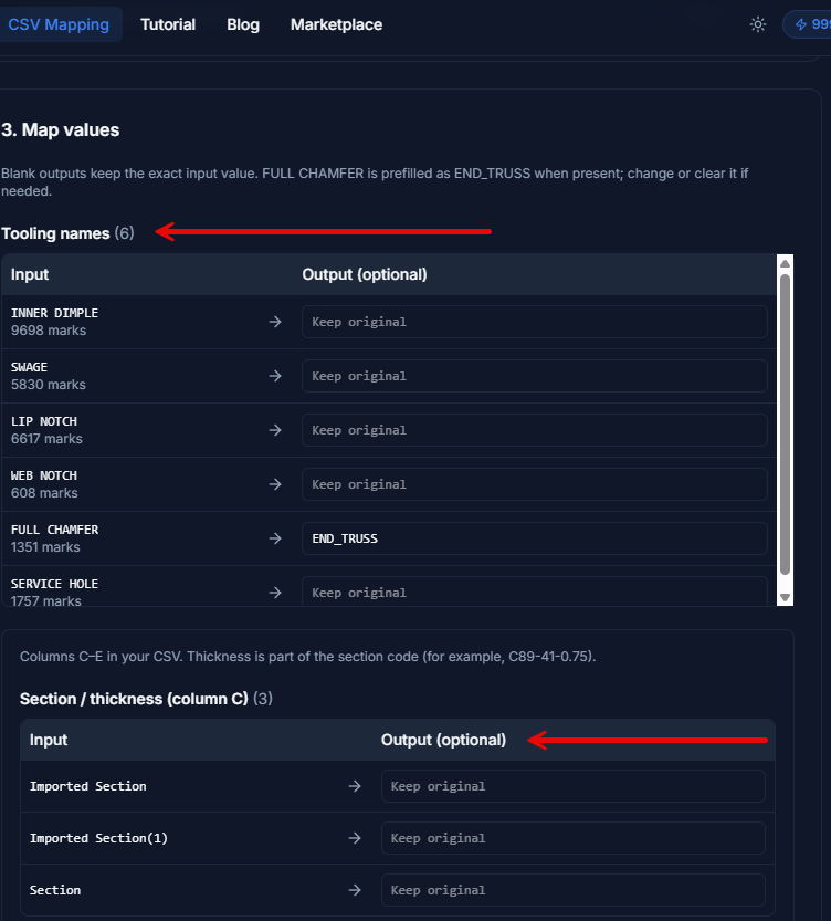
The tool reads the source columns and presents the imported values for mapping. You can save a mapping configuration in this browser for reuse; it is browser-local and is not a signed .clgs machine configuration. A blank output mapping means “preserve the original value” for that field.
Section/thickness: map the source field Imported Section, Imported Section(1), or Section to the confirmed section code (for example, C89-41-0.75). The section/thickness value appears in source column C. Confirm the actual material gauge for every section; never infer or guess gauge from a section name.
Member type: column D.
Orientation: column E.
Stick names: optionally map names when your downstream workflow requires them.
Tooling names: map machine-specific output names when needed. Leave the output blank to preserve the original name.
FULL CHAMFER: the default is a rename to END_TRUSS. This is a name change only; it does not create new tooling.
Map source values deliberately. In particular, use the imported section value from column C and an independently confirmed gauge.
FILLER rows and download choices
FILLER rows are excluded by default when present. Uncheck the expandable removal option to retain them. Collapsing the control only hides its details; it does not change whether FILLER removal is enabled.
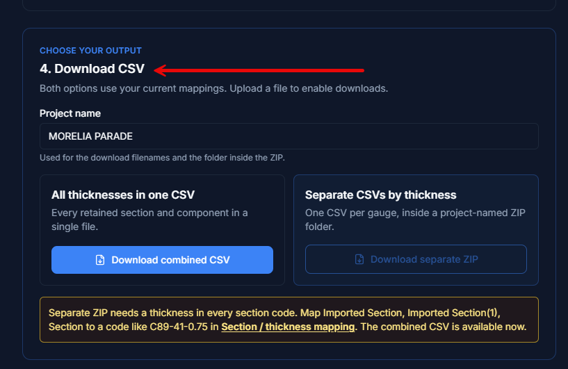
Enter a project name, then choose one combined CSV, a ZIP with separate CSVs per thickness, or Download frames ZIP for one individual CSV per frame. Each ZIP contains a project-named folder. Frame ZIP downloads do not require thickness codes; frame names must be identifiable from the mapped member names or an explicit frame header. A combined CSV remains available even when gauge information is incomplete. A per-thickness ZIP requires a valid numeric gauge in the section code for every retained section before it can be created.
Payment gate — US$0.03 per linear metre
All download choices require a server-verified export. Review the retained component length and confirm the payment gate.
Length includes component quantities; removed FILLER rows are not charged. The ZIP is billed on the total retained length,
not once per file. Existing subscription allowance and LM credits are used first. If your balance is insufficient,
use the existing payment/top-up options before downloading. Mapping and reviewing values does not deduct credits.
Choose the project name and output format. The per-thickness ZIP is available only when every retained section has a valid numeric gauge in its section code.
Verify machine-specific names before production
Tooling names are machine-specific. Confirm the mapped names with your factory before loading output to a machine. CSV Mapping maps or renames values; it does not recalculate tooling stations or member lengths.
9Export Validation Report
The Export Validation Report verifies that every frame has tooling marks correctly stored before you generate the CSV. Click Validate Export in the Frame Editor header to open the report.
Status Filter
Three filter buttons appear at the top of the report:
Filter
Shows
All (N)
Every frame in the conversion.
Verified (N)
Frames with at least one stored tooling mark — ready for export.
Unverified (N)
Frames with zero stored marks — require review before export.
Navigating from the Report
Frame row — click any row to close the report and navigate the Frame Editor to that frame. A → indicator appears on hover.
Member row (expand the frame to show members) — click a member row to navigate to the frame and select that specific member in the Member Inspector.
Position Mismatch Warnings
For repeated frames (same base name, different suffix like -2, -3), LGSConverter compares punch-centre positions against the first instance. Differences greater than 3 mm trigger a Position Mismatch warning. Open the affected frames, compare geometry, and re-run Generate Machine File once resolved.
10QA & Auto-Fix
After conversion, LGSConverter runs an automatic quality-assurance pass across all frames. Results appear in the QA Summary at the top of the Frame Editor panel.
QA checks performed
Member classification consistency (stud vs plate vs diagonal vs brace)
Profile dimension validity (positive web, flange, and lip lengths)
Frame envelope integrity (all members inside the declared panel boundary)
Clone–master geometry match (within tolerance)
Opening stud presence (TRIM/JACK/KING studs around declared openings)
Tooling coverage (no connection left without marks)
Auto-Fix (IFC conversions)
Click Apply Auto-Fix to run automatic corrections server-side. The QA summary updates to show which issues were resolved. Issues that cannot be auto-fixed are listed under "Still require manual attention" — address these in the Frame Editor before exporting.
Do not skip QA review
Exporting a CSV from a frame with unresolved QA issues may produce incorrect tooling positions on the roll-former. Always resolve or acknowledge all issues before production.
11AI Tool Check Overlay
The AI Tool Check is a best-effort advisory layer that flags connections whose tooling may need attention. Toggle it on/off using the AI Tool Check button in the Frame Editor toolbar.
Flagged junctions are highlighted in orange with a brief reason (e.g., "Expected SWAGE not found").
A badge shows the count of flagged items for the current frame. Zero on a fully-tooled frame is the correct result.
Requests are automatically invalidated when you edit or navigate to a new frame.
AI Tool Check is advisory only
This overlay does not modify tooling marks or affect the CSV export. Use the Export Validation Report (Section 9) to confirm what will actually be written to CSV.
12Downloading Your Export
Immediate ZIP download (IFC / XML)
After conversion, a Download ZIP button appears in the result panel. This regenerates a fresh ZIP from the current live-edited frame state — always reflecting your latest edits and exclusions.
Machine CSV
Available via Generate Machine File in the Frame Editor. See Section 8.4.
Downloads are always regenerated
Every click of Download or Generate Machine File recomputes the export from the current frame state. There is no stale cached download — edits and exclusions are always included.
Billing and linear metres
Billing is calculated on the total linear metres of included frames at the time of download. The running LM total is shown in the Frame Editor header. Excluded frames are not billed.
13Desktop Application (Windows)
LGSConverter is also available as a Windows desktop application — a standalone installer that runs natively on Windows 10 and 11. The desktop app provides the same conversion and machine CSV export capabilities as the web platform, with a local graphical interface.
Do not use these activation steps for RFY MAPPER
This section describes the LGSConverter desktop app and its own license. RFY MAPPER is a separate application with a one-time 500 LM introductory allowance and prepaid PAYG purchases. It does not use an LGSConverter license key. See the RFY MAPPER User Manual.
🔑
License key authentication
No browser login required. A one-time license key is entered on first run and stored securely on the machine.
📁
Local file workflow
Open files directly from your Windows file system. No drag-and-drop browser upload needed.
⚙️
Custom machine profile
Configure CUSTOM machine mappings with a built-in tool code editor, then save and load .clgs files locally.
🔄
Auto-update
The app checks for a new version on startup and prompts you to download the latest installer automatically.
Installing the desktop application
Download LGSConverter-Setup.exe from your account dashboard or from the link provided by LGSConverter support.
Run the installer. Windows may show a SmartScreen prompt — click More info → Run anyway (the installer is unsigned but safe to run).
Follow the installation wizard. LGSConverter installs to C:\Program Files\LGSConverter by default.
Launch LGSConverter from the Start menu or the desktop shortcut.
Activating your license key
On first launch, the License panel opens automatically.
Enter your license key in the text box (format: XXXX-XXXX-XXXX-XXXX).
Click Activate. The app validates the key with the LGSConverter server.
Once activated, the key is stored in %USERPROFILE%\.lgs-converter\license.key and is loaded automatically on future launches.
License expiry warnings
The desktop app checks the remaining validity of your license key in the background on each launch. You will receive on-screen warnings when the key is approaching expiry — typically at 30 days and 7 days remaining. Contact LGSConverter support to renew before expiry.
Seat limits
Each license key is tied to a maximum number of concurrent machines (seats). If you exceed the seat limit, the activation will be rejected. Contact support to add seats or deactivate an old machine.
Converting a file in the desktop app
Click Open File… in the toolbar and select your .ifc, .xml, .fcp, or .csv file.
The app sends the file to the LGSConverter API and displays the conversion result.
Use the built-in frame viewer to review the output, then click Generate CSV to produce the machine file.
Choose a save location for the CSV. The file is written directly to your local disk.
Loading a custom machine config (.clgs) in the desktop app
In the toolbar, click Machine Config → Load .clgs…
Browse to your .clgs file and click Open.
The app validates the signature. If valid, the custom mapping activates immediately.
The current mapping is auto-saved to %USERPROFILE%\.lgs-converter\custom.clgs and restored on the next launch.
Portable version
A portable (no-installer) version of the desktop app is available for environments where installing software requires administrator approval. Download LGSConverter-Portable.zip from your account dashboard, extract to any folder, and run LGSConverter.exe directly. License key activation works identically to the installed version.
Which version to use?
The web platform is recommended for most users — it always runs the latest version with no installation required. The desktop app is best suited for environments with restricted internet browsers, high-volume batch workflows, or users who prefer a native Windows interface.
14LGS Design Marketplace
The LGS Design Marketplace is an integrated store where designers and fabricators can publish and purchase ready-to-convert LGS design packages.
Purchasing a design
Browse the Marketplace from the Marketplace tab.
Click any listing to view the detail page, including 3D previews and specifications.
Click Purchase and complete checkout via the secure payment gateway.
Download the source files from your account or the confirmation email.
Upload the downloaded file to LGSConverter to begin converting immediately.
Selling a design
To list your designs for sale, contact the LGSConverter team via the Become a Seller form in the Marketplace. Sellers receive a percentage of each sale after platform commission.
15Troubleshooting
Symptom
Likely cause
Resolution
Frame Editor is blank after conversion
Detail token not returned (large file or server timeout)
Wait 15 seconds and refresh. For large projects, split the ZIP into smaller batches.
IFC conversion returns same result after editing source
IFC Redis cache serving previous parse
Rename the file slightly before re-uploading to bypass the cache.
Tooling marks missing from some frames
Frames not retooled after editing
Open each affected frame. Use the Validation Report to identify unverified frames and trigger a retool pass.
Machine CSV has unexpected tool codes
Wrong machine profile or incomplete mapping
Open Configure Mapping and verify all tool types are correctly mapped.
.clgs file rejected on upload
File edited after signing (invalid HMAC)
Do not edit .clgs files manually. Request a new signed file from support.
Desktop app license activation fails
Seat limit reached, key expired, or no internet
Check internet connectivity. Contact support to add seats or renew the key.
Position mismatch warning in Validation Report
Repeated frame copies retooled independently
Open each flagged frame, compare member geometry, ensure all copies are consistent, then re-export.
.lgs file fails to load
Wrong account or corrupted file
Ensure you are logged in with the same account that saved the file. Download a fresh copy if the file may be corrupted.
Download generates a 500 error
Frame serialisation failure (non-standard member type)
Check the QA Summary for classification errors. Exclude the affected frame if not required for this run.
Getting support
Use the Help link in the navigation bar to open a support request. Include: your browser or app version, file format, and a description of the symptom. Attach your source file or .lgs session file if possible — this allows the support team to reproduce the issue directly.
16Disclaimer & Copyright
Software Disclaimer
LGSConverter is provided as a production-assist tool to help fabricators convert structural framing models into machine-readable CSV files. While every effort has been made to ensure the accuracy of the tooling marks, station positions, and member classifications produced by this software, all machine output must be reviewed and approved by a qualified LGS engineer or detailer before production commences.
LGSConverter derives tooling marks from geometric analysis of the uploaded source file. The accuracy of the output is contingent on the accuracy of the source model. LGSConverter accepts no liability for errors or omissions in the source model; for incorrect machine codes resulting from an incorrectly configured tool mapping; or for any loss or damage arising from the use of generated machine files without adequate engineering review.
The AI Tool Check overlay is advisory only. It does not constitute engineering approval and must not be used as a substitute for a qualified engineer's review. Marks flagged by AI Tool Check may be correct; marks not flagged may still be incorrect.
The desktop application communicates with the LGSConverter cloud API to perform conversions. An active internet connection is required. LGSConverter reserves the right to modify, suspend, or discontinue any feature or service at any time without notice.
This software is not affiliated with, endorsed by, or produced by FRAMECAD Group Limited. FRAMECAD, FRAMECAD Detailer, and related product names are trademarks of FRAMECAD Group Limited. Reference to these names is solely for the purpose of describing file format compatibility.
This document and the software it describes are protected by copyright law. No part of this document may be reproduced, distributed, transmitted, or adapted in any form or by any means — electronic, mechanical, photocopying, recording, or otherwise — without the prior written permission of LGSConverter.
Unauthorised copying, redistribution, or modification of this document or the LGSConverter software is strictly prohibited and may result in civil and criminal liability.
The LGSConverter name, logo, and related marks are the intellectual property of LGSConverter. All third-party trademarks referenced in this document are the property of their respective owners.